I recently spent some time battling Juniper’s poor documentation in an attempt to get PPPoE subscriber termination within VPLS Pseudowire Subscriber Logical Interfaces.
I tested this on an MX10003 running JunOS 19.1R3.9.
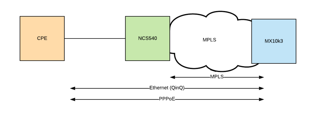
The topology is fairly straight forwards. There is a CPE that is generating double tagged PPPoE frames towards the network. The intention is to get a Cisco NCS540 encapsulating these frames into a VPLS instance, forwarding over the MPLS network to a Juniper MX100003, which then terminates the PPPoE session.
The VPLS part of the configuration is completely standard, so I won’t document here.
Configuration
To get started, a few things need to be enabled on the box.
- Pseudowire Subscriber Interfaces (Similar to Aggregated Ethernet Interfaces)
- Tunnel Services
chassis {
    pseudowire-service {
        device-count 2048;
    }
    fpc 1 {
        pic 1 {
            tunnel-services {
                bandwidth 100g;
            }
        }
    }
}
Next we need to create two dynamic profiles to attach to the virtual interfaces.
The first is for the virtual interface that gets created and installed into the VPLS. As each subscriber can be on a different set of VLANs this needs creating dynamically. If your subscribers are only single tagged, this configuration would be altered to only use a single VLAN.
The second is the subscriber template. This can contain a lot of attributes that can get populated by RADIUS, such as routing instance and IP address. I’ve not dug too deep into RADIUS integration at this point, but I would expect that part of it to be reasonably simple.
dynamic-profiles {
    vlan-double-tag {
        interfaces {
            "$junos-interface-ifd-name" {
                unit "$junos-interface-unit" {
                    no-traps;
                    vlan-tags outer "$junos-stacked-vlan-id" inner "$junos-vlan-id";
                    family pppoe {
                        dynamic-profile pppoe-profile;
                    }
                }
            }
        }
    }
    pppoe-profile {
        interfaces {
            pp0 {
                unit "$junos-interface-unit" {
                    no-traps;
                    ppp-options {
                        chap;
                    }
                    pppoe-options {
                        underlying-interface "$junos-underlying-interface";
                        server;
                    }
                    family inet {
                        unnumbered-address lo0.0;
                    }
                }
            }
        }
    }
}
Next comes the interface that is placed into the VPLS. It is important to note that the accept line limits the type of packets that are allowed to create a virtual interface. When I was initially testing I had this set to pppoe, which I would have expected to work as they are PPPoE frames. This apparently is not the case, as the frames on this particular interface are seen as ‘VLAN’ frames.
Update 05/08/2020: I raised this behaviour to Juniper, and this is a bug. https://prsearch.juniper.net/InfoCenter/index?page=prcontent&id=PR1523902
If your subscribers are only single tagged, this configuration would also be altered to only use a single VLAN.
When I had this set to pppoe, I did a packet capture on the ps0.32767 interface (which is the magic interface that control packets come in on). I could see PADI messages come in, but nothing come out.
interfaces {
    ps0 {
        anchor-point {
            lt-1/1/0;
        }
        flexible-vlan-tagging;
        auto-configure {
            stacked-vlan-ranges {
                dynamic-profile vlan-double-tag {
                    accept [ pppoe any ];
                    ranges {
                        any,any;
                    }
                }
                access-profile PPPoE-Client;
            }
            remove-when-no-subscribers;
        }
        unit 0 {
            encapsulation ethernet-vpls;
        }
    }
}
Next create an access profile. This is where the RADIUS server configuration would go, but for this testing I’ve just configured a single static user.
access {
    profile PPPoE-Client {
        authentication-order password;
        subscriber "testuser@domain" {
            password "$9$j9kfz3nCApBDiPQF/0O"; ## SECRET-DATA
            framed-ip-address 130.0.0.1;
        }
    }
}
access-profile PPPoE-Client;
Finally attach the ps0 interface into a VPLS instance. This is the final piece of the puzzle, and subscribers should now be able to connect.
routing-instances {
    BGP-VPLS-TESTING {
        instance-type vpls;
        interface ps0.0;
        route-distinguisher 1.2.3.4:3;
        vrf-target target:64512:1;
        protocols {
            vpls {
                site 3 {
                    site-identifier 3;
                }
                vpls-id 2020;
            }
        }
    }
}
Diagnostics
There are several useful commands that I’ve discovered in working out what is going on. In order to see all the PPP control messages that are occuring, you can monitor the traffic on ps0.32767.
admin@mx10k3> monitor traffic interface ps0.32767 extensive no-resolve
Address resolution is OFF.
Listening on ps0.32767, capture size 1514 bytes
17:49:47.619681  In
    Juniper PCAP Flags [Ext, In], PCAP Extension(s) total length 22
      Device Media Type Extension TLV #3, length 1, value: Ethernet (1)
      Logical Interface Encapsulation Extension TLV #6, length 1, value: Ethernet (14)
      Device Interface Index Extension TLV #1, length 2, value: 215
      Logical Interface Index Extension TLV #4, length 4, value: 113
      Logical Unit Number Extension TLV #5, length 4, value: 32767
    -----original packet-----
    00:10:94:00:00:01 > ff:ff:ff:ff:ff:ff, ethertype 802.1Q (0x8100), length 32: vlan 2, p 7, ethertype 802.1Q, vlan 3, p 7, ethertype PPPoE D, PPPoE PADI
17:49:47.620367 Out
    Juniper PCAP Flags [Ext], PCAP Extension(s) total length 22
      Device Media Type Extension TLV #3, length 1, value: Ethernet (1)
      Logical Interface Encapsulation Extension TLV #6, length 1, value: Ethernet (14)
      Device Interface Index Extension TLV #1, length 2, value: 215
      Logical Interface Index Extension TLV #4, length 4, value: 113
      Logical Unit Number Extension TLV #5, length 4, value: 32767
    -----original packet-----
    f2:7c:c7:af:7b:c3 > 00:10:94:00:00:01, ethertype 802.1Q (0x8100), length 73: vlan 2, p 6, ethertype 802.1Q, vlan 3, p 6, ethertype PPPoE D, PPPoE PADO [AC-Name "mx10k3"] [Service-Name] [AC-Cookie UTF8]
Here you can see lots of useful information, including the VLANs that are in use – here an S-TAG of 2, and a C-TAG of 3, as well as the full end-to-end PPP messages. It is possible to write this file to a PCAP for examination in wireshark or similar if you need to examine the full frames that are being sent. As far as I can tell it’s only possible to receive the control messages. User traffic is not exposed in this way.
The show subscriber commands demonstrate the two virtual interfaces that are created. One for the interface that is generated from the VPLS, and the other for the subscriber.
admin@mx10k3> show subscribers
Interface             IP Address/VLAN ID                      User Name                      LS:RI
ps0.3221237566        0x8100.2 0x8100.3                                                 default:default
pp0.3221237567        130.0.0.1                               testuser@domain           default:default

admin@mx10k3> show subscribers extensive
Type: VLAN
Logical System: default
Routing Instance: default
Interface: ps0.3221237566
Interface type: Dynamic
Underlying Interface: ps0
Dynamic Profile Name: vlan-double-tag
State: Active
Session ID: 12103
PFE Flow ID: 12197
Stacked VLAN Id: 0x8100.2
VLAN Id: 0x8100.3
Login Time: 2020-06-29 17:54:21 UTC

Type: PPPoE
User Name: testuser@domain
IP Address: 130.0.0.1
IP Netmask: 255.255.255.255
Logical System: default
Routing Instance: default
Interface: pp0.3221237567
Interface type: Dynamic
Underlying Interface: ps0.3221237566
Dynamic Profile Name: pppoe-profile
MAC Address: 00:10:94:00:00:01
State: Active
Radius Accounting ID: 12104
Session ID: 12104
PFE Flow ID: 12198
Stacked VLAN Id: 2
VLAN Id: 3
Login Time: 2020-06-29 17:54:21 UTC
Conclusion
All in all, the configuration required to get this working is reasonably straight forward. Unfortunately the documentation on Juniper’s website is pretty lacklustre, but this has only been getting worse over the years.
My next challenge is to get this working in an EVPN. I believe the features are supported, so hopefully with what I have learnt with VPLS it should be straight forward.
Useful Links
Some useful links I found
Hi,
Any luck with EVPN.
I’ve not had a chance to lab it yet. We did have a roadmap session with Juniper recently who said this wouldn’t be available till 1H 2021.
Got this working,
Single routing instance for entire BNG network acting as hub and spoke.
BNG
root@bng1> show configuration routing-instances EVPN
instance-type evpn;
interface lt-0/0/0.0;
route-distinguisher 65000:999;
vrf-export BNG-ONLY;
vrf-target target:65000:999;
protocols {
evpn {
interface lt-0/0/0.0;
}
Export policy to alter BNG ps interface route community
policy-statement BNG-ONLY {
term 0 {
from protocol evpn;
then {
community add BNG;
accept;
}
}
term 1 {
then reject;
community BNG members target:65000:111;
PS interface configuration for PPPOE termination
root@bng1> show configuration interfaces ps0
anchor-point {
lt-0/0/0;
}
flexible-vlan-tagging;
auto-configure {
stacked-vlan-ranges {
dynamic-profile TOWERS {
accept pppoe;
ranges {
50-50,any;
51-51,any;
}
access-profile COMTEL;
}
dynamic-profile BACKUP {
accept pppoe;
ranges {
666-666,any;
}
access-profile COMTEL;
}
}
}
encapsulation flexible-ethernet-services;
unit 0 {
encapsulation ethernet-ccc;
}
ACCESS
Same instance for all WISPS
root@mx1> show configuration routing-instances
EVPN {
instance-type evpn;
interface ge-0/0/3.0;
route-distinguisher 65000:999;
vrf-import BNG-ONLY;
vrf-target target:65000:999;
protocols {
evpn {
interface ge-0/0/3.0;
}
Single logical unit for all WISPS
Just add your wisp outer value in the list
root@mx1> show configuration interfaces ge-0/0/3
description “PPPOE USERS (EVPN)”;
flexible-vlan-tagging;
mtu 2000;
encapsulation flexible-ethernet-services;
unit 0 {
encapsulation vlan-bridge;
vlan-id-list 50-51;
}
Policy to import only the MAC table entry of the BNG you need to connect to
This will allow you to only install the MAC of your BNG and not other access site. This way broadcasts won’t propagate through the entire EVPN entry points.
policy-statement BNG-ONLY {
term 0 {
from community BNG;
then accept;
}
term 1 {
then reject;
}
community BNG members target:65000:111;
As per output only your local connected Wisp and the Mac of your chosen BNG seen, no other remote WISP’s details.
root@mx1> show evpn database
Instance: EVPN
VLAN DomainId MAC address Active source Timestamp IP address
00:05:86:9b:26:00 172.16.0.6 Mar 13 10:10:26
50:02:00:13:00:02 ge-0/0/3.0 Mar 12 23:49:5
How to use EVPN and PS termination in one setup
root@bng1> show configuration routing-instances EVPN
instance-type evpn;
interface lt-0/0/0.0;
route-distinguisher 65000:999;
vrf-export BNG-ONLY;
vrf-target target:65000:999;
protocols {
evpn {
interface lt-0/0/0.0;
root@bng1> show configuration interfaces lt-0/0/0
unit 0 {
encapsulation ethernet-bridge;
peer-unit 1;
}
unit 1 {
encapsulation ethernet-ccc;
peer-unit 0;
root@bng1> show configuration protocols l2circuit
local-switching {
interface ps0.0 {
end-interface {
interface lt-0/0/0.1;
}
ignore-encapsulation-mismatch;
ignore-mtu-mismatch;
root@bng1> show configuration interfaces ps0
anchor-point {
lt-0/0/0;
}
flexible-vlan-tagging;
auto-configure {
stacked-vlan-ranges {
dynamic-profile TOWERS {
accept pppoe;
ranges {
50-50,any;
103-103,any;
51-51,any;
}
access-profile COMTEL;
}
dynamic-profile BACKUP {
accept pppoe;
ranges {
666-666,any;
}
access-profile COMTEL;
}
}
}
encapsulation flexible-ethernet-services;
unit 0 {
encapsulation ethernet-ccc;
}